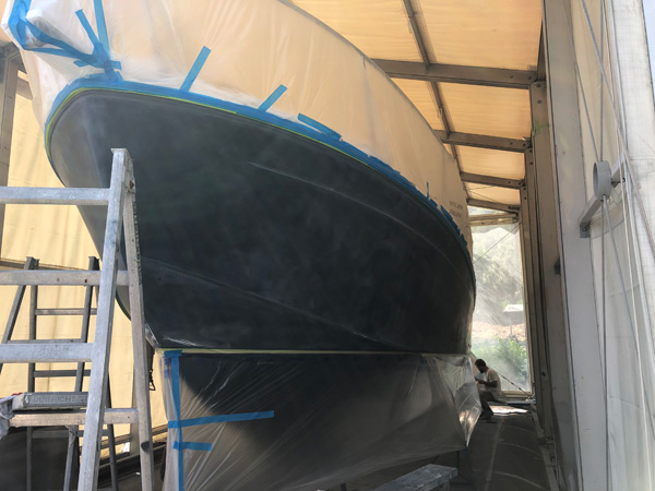
Boat blistering is a common issue that many boat owners face over time. This problem typically occurs due to the buildup of water under the gel coat, which can lead to visible bubbles or blisters on the hull. Blistering is not only unsightly but can also weaken the structural integrity of the vessel, which is why addressing the issue promptly is essential for maintaining the boat’s durability and safety. Fortunately, there are effective solutions available that can restore the strength of the hull and prevent further damage. The key to fixing blistering lies in treating the root cause, which is the water trapped beneath the outer surface of the boat. This water is often the result of moisture infiltration due to prolonged exposure to water or improper maintenance. Over time, the moisture leads to the breakdown of the resin used in the boat’s construction, resulting in the formation of blisters. Addressing this problem requires removing the moisture and repairing the underlying damage. The repair process typically begins with a thorough inspection to assess the extent of the blistering and determine the best course of action.

Once the extent of the damage is established, the next step is to prepare the surface for repair. This involves sanding down the affected areas to remove the blistered gel coat and expose the underlying fiberglass. It is essential to carefully remove all traces of damaged material to ensure a smooth, clean surface for the new layers of resin or gel coat. In some cases, additional treatments may be required to remove any moisture still trapped inside the hull. This can be achieved through the use of specialized drying agents or heat sources, which help eliminate the moisture completely before the repair process continues. After preparing the surface, the repair solution is applied to the hull. This typically involves the application of a high-quality resin that bonds seamlessly with the boat’s original fiberglass structure. The resin is carefully spread over the affected areas, ensuring complete coverage of the exposed surface. Once the resin has cured, a new layer of gel coat can be applied to restore the smooth, glossy finish that the boat once had.
This step not only improves the boat blisters appearance but also adds an extra layer of protection against future blistering and environmental damage. To ensure the long-term effectiveness of the repair, it is essential to follow up with regular maintenance and inspections. Blistering can occur again if moisture continues to penetrate the hull, so keeping the boat dry and maintaining the integrity of the surface is critical. Regularly cleaning the hull, inspecting the gel coat for any signs of damage, and applying protective coatings can help extend the life of the boat and prevent future blistering. In conclusion, boat blistering is a serious issue that can compromise the strength and appearance of a vessel. However, with the right repair solution, the hull can be restored to its original condition, maintaining its durability and aesthetic appeal. Through proper preparation, application of high-quality repair materials, and ongoing maintenance, boat owners can effectively address blistering issues and enjoy a long-lasting, resilient vessel.


